
Failure Mode and Effects Analysis (FMEA) is a systematic, bottom-up analytical discipline used to identify, evaluate, and mitigate potential design or process failures before they manifest in physical operations. By methodically analyzing how individual components can fail and evaluating the cascading effects of those failures, FMEA ensures that robotic systems whether deployed in industrial manufacturing, healthcare environments, or commercial spaces, operate with high reliability and safety.
While FMEA is not universally mandated across every engineering domain, it is highly recommended, and often required, by major international standards and regulatory bodies. Executing an FMEA early in the design phase allows engineering teams to catch potential hardware and software vulnerabilities before they escalate into expensive design re-spins, product recalls, or field failures. In highly regulated sectors such as aerospace, defense, automotive, and medical devices, FMEA serves as a core technical record proving that systematic risks have been identified and mitigated.
Integrating FMEA Across the System Lifecycle
To maximize its effectiveness, an FMEA must be initiated early in the product development lifecycle and treated as a living engineering repository that evolves alongside the system architecture.
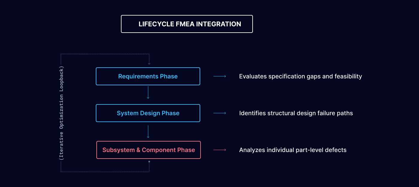
Requirements Analysis Phase:
Executing an FMEA at this initial stage helps identify potential failure modes embedded within the technical specifications themselves. This validation step ensures that system requirements are clear, complete, and technically feasible before layout work begins.
System Design Phase:
Conducting an FMEA at the macro-level architecture helps identify failure propagation paths between interacting subsystems, ensuring that the overall system layout incorporates adequate fault isolation barriers.
Subsystem and Component Phase:
At this granular level, the FMEA evaluates specific electrical components, mechanical joints, and software modules, verifying that each element is designed to meet target safety and reliability metrics.
Step-by-Step FMEA Execution Framework
1. Assemble a Cross-Functional Engineering Team
An FMEA cannot be successfully executed by a single engineer working in isolation. It requires a dedicated, multi-disciplinary team of subject matter experts to evaluate the system from different perspectives. The core analysis group must include representatives from software engineering, hardware design, systems engineering, test engineering, and field operations to ensure that all mechanical, electrical, and algorithmic failure paths are explored.
2. Define the Analytical Scope
Establish clear physical and functional boundaries for the analysis. The engineering team must document exactly what is included and excluded from the review. Specifying whether the FMEA evaluates an isolated mechanism (such as a robotic end-effector), a complete machine (an autonomous mobile robot), or an entire multi-stage assembly line. Locking in the scope prevents analytical drift and concentrates engineering hours where they are needed most.
3. Identify Systemic Failure Modes
Methodically list every conceivable way that each component, software routine, or process step within the defined scope can fail to fulfill its intended function. Engineers must evaluate worst-case scenarios, tracking failure modes ranging from hardware defects like motor coil burnouts and structural joint fractures to software anomalies like sensor data drops or communication timeouts.
4. Analyze Cascading Effects
For each identified failure mode, the team must determine its immediate and long-term impact on system behavior. Engineers evaluate whether a local component failure triggers a minor performance degradation, causes a localized shutdown, or escalates into a catastrophic hazardous event affecting operators or surrounding assets. This evaluation is critical to prioritize which failures demand immediate mitigation.
5. Determine Root Causes
Dig down into the underlying physics of failure or software logic gaps to isolate the root cause of each failure mode. Engineers must verify whether the trigger stems from a fundamental design flaw, an environmental factor, a manufacturing variation, or a maintenance oversight. Pinpointing the exact cause allows teams to develop highly targeted, effective design fixes.
6. Evaluate Existing Engineering Controls
Before proposing design updates, document the current preventative and protective measures integrated into the existing design. This involves mapping out the diagnostic sensors, automated software alarms, physical guards, and preventative maintenance schedules currently tasked with detecting or preventing the failure mode before it reaches the end user.
7. Calculate Risk Priority Numbers (RPN)
To quantify and prioritize the risks identified during the analysis, the cross-functional team scores each failure mode across three distinct engineering dimensions using a standard 1-to-10 ranking scale:
Severity (S):
Measures the absolute consequence of the failure effect on a scale from 1 (no noticeable impact) to 10 (catastrophic safety hazard or regulatory breach).
Occurrence (O):
Estimates the probability or physical frequency of the failure cause manifesting during the product's operational lifespan.
Detection (D):
Rates the likelihood that existing design controls or internal diagnostics will successfully identify the fault before the system executes a dangerous action. A score of 1 indicates certain detection, while 10 indicates the fault is completely undetectable.
The team then multiplies these three independent metrics together to compute the Risk Priority Number (RPN):
RPN = Severity x Occurrence x Detection
Failure modes that return high RPN values represent critical design vulnerabilities and must be addressed immediately by the engineering division.
8. Develop and Execute Action Plans
Using the compiled RPN matrix as a strategic roadmap, engineers must design and implement targeted action plans to eliminate or minimize the risks associated with high-priority failure modes. These technical mitigations typically involve:
Redesigning components or selecting higher-grade, safety-rated hardware to lower the Occurrence score.
Introducing hardware redundancy or fail-safe operational modes to minimize the Severity score.
Implementing advanced software diagnostic algorithms or hardware monitoring loops to improve the Detection score.
9. Implement Continuous Monitoring
Following the implementation of design mitigations, the FMEA team must re-evaluate the system to calculate a updated residual RPN. Continuous operational monitoring and field telemetry tracking ensure that the chosen engineering controls work effectively in the field and help catch any emerging system anomalies before they result in operational downtime.
Core Engineering Benefits of FMEA
Targeted Risk Reduction:
Systematically exposing hidden failure modes allows organizations to neutralize mechanical, electrical, and algorithmic hazards before they trigger field incidents.
Elevated System Reliability:
Incorporating FMEA outputs directly into early design sprints results in highly robust architectures capable of maintaining long-term uptime and consistent operational throughput.
Significant Lifecycle Cost Savings:
Identifying and resolving structural vulnerabilities during the virtual design and requirement phases avoids incredibly expensive late-stage tooling re-works, software patches, and field product recalls.
Validated Operational Safety:
For companies deploying high-integrity systems within the aerospace, automotive, healthcare, and industrial sectors, FMEA provides the definitive, audit-ready engineering record required to satisfy international compliance auditors and secure market access.